- Welcome to Analog-Precision Board.

Taking Audio Reproduction to the Next Level.......
Recent posts
#71
Performance and Measurements / Buffered Output from the clock...
Last post by Tranquility Bass - November 19, 2020, 08:25:22 PMMinimal overshoot and ringing with a well defined transition period !

#72
Performance and Measurements / Buffered Output from the clock...
Last post by Tranquility Bass - November 19, 2020, 08:24:17 PMAs smooth as 

#73
Performance and Measurements / Raw Output from the master clo...
Last post by Tranquility Bass - November 19, 2020, 08:23:10 PMVery well defined with no overshoot and smooth crossover transition !

#74
Performance and Measurements / Frequency Measurement
Last post by Tranquility Bass - November 19, 2020, 08:19:11 PMFrequency is pretty much spot on !!

#75
Performance and Measurements / Clock Fidelity Test
Last post by Tranquility Bass - November 19, 2020, 07:02:18 PMTest Methodology:
In these tests we are using a wide bandwidth digital scope to view the 49.152MHz master clock waveform at various points in the clock network. It is impossible to make proper measurements of a clock source unless you use a scope with a suitable bandwidth that can at least capture the 21st harmonic of the fundamental frequency of the clock frequency which means a scope with at least a 1GHz bandwidth. Not only that you need to use a probe with an equivalent or greater bandwidth to the scope and preferably an active probe to minimize loading.
To avoid loading down the device under test we use an active probe (Tek P6204) with at least 1GHz bandwidth along with the shortest ground connection to minimize loop inductance in the probe which would manifest itself as ringing in the waveform. We used a Tektronix TDS784A DSO scope with a 1GHz bandwidth and real time sampling rate of 4Gs/s as well as a 10Gs/s equivalent time sampling rate for our measurements. For the expanded scale measurement the scope was set to an equivalent sampling rate of 100 Gs/s. What we are looking for is minimum ringing and overshoot without any kinks in the clock transition interval.
Test Results:
Conclusion:
As one can see from the scope shots below that in all cases the clock wave-forms are clean and stable and show minimum overshoot which means that the clock outputs are properly matched to the board traces in order to minimize transmission line effects and reflections.

Tektronix P6204 Low Capacitance Active Probe with 1GHz bandwidth

Active Probe applied to clock circuit using the shortest possible ground connection for minimum induced ringing and overshoot

In these tests we are using a wide bandwidth digital scope to view the 49.152MHz master clock waveform at various points in the clock network. It is impossible to make proper measurements of a clock source unless you use a scope with a suitable bandwidth that can at least capture the 21st harmonic of the fundamental frequency of the clock frequency which means a scope with at least a 1GHz bandwidth. Not only that you need to use a probe with an equivalent or greater bandwidth to the scope and preferably an active probe to minimize loading.
To avoid loading down the device under test we use an active probe (Tek P6204) with at least 1GHz bandwidth along with the shortest ground connection to minimize loop inductance in the probe which would manifest itself as ringing in the waveform. We used a Tektronix TDS784A DSO scope with a 1GHz bandwidth and real time sampling rate of 4Gs/s as well as a 10Gs/s equivalent time sampling rate for our measurements. For the expanded scale measurement the scope was set to an equivalent sampling rate of 100 Gs/s. What we are looking for is minimum ringing and overshoot without any kinks in the clock transition interval.
Test Results:
- Frequency Measurement
- Raw Output from the master clock oscillator
- Buffered Output from the clock buffer chip feeding the DAC
- Buffered Output from the clock buffer chip feeding the ADC
- Buffered Output from the clock buffer chip feeding the timing logic !
Conclusion:
As one can see from the scope shots below that in all cases the clock wave-forms are clean and stable and show minimum overshoot which means that the clock outputs are properly matched to the board traces in order to minimize transmission line effects and reflections.
Tektronix P6204 Low Capacitance Active Probe with 1GHz bandwidth
Active Probe applied to clock circuit using the shortest possible ground connection for minimum induced ringing and overshoot
#76
News Updates / UP Extensive Measurements now ...
Last post by Tranquility Bass - October 20, 2020, 05:59:36 PMThe Latest test results and measurements from our Lab show the Ultimate-Preamplifer 2/+ meets or exceeds its design objectives by a huge margin ! Click here to view more.
#77
Performance and Measurements / Noise Performance (Unbalanced ...
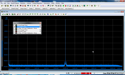
Last post by Tranquility Bass - October 18, 2020, 06:39:21 PMSome mains induced noise caused by leakage flux from the transformer coupling into the unbalanced connections between the DSP board and the unbalanced output boards in the same way earth loops are setup in unbalanced connections between equipment !. The balanced outputs do not exhibit this since the balanced connections between the boards cancels out the mains induced noise ! However the mains induced noise components on the unbalanced outputs is still 120dB below the reference level so we don't have to lose any sleep over this

#78
Performance and Measurements / Noise Performance (Balanced ou...
Last post by Tranquility Bass - October 18, 2020, 06:37:33 PM #79
Performance and Measurements / Re: AES17 - THD+N vs Frequency...
Last post by Tranquility Bass - October 04, 2020, 01:35:47 PM #80